2-spindle turning, milling centre with 8 axes for brake callipers
Fully automated manufacturing cell
- Complete machining on one machine bed in 2 set-ups
- Cycle time 240 sec.
- 20 driven tools
- Quality assurance via measuring probe in OP10

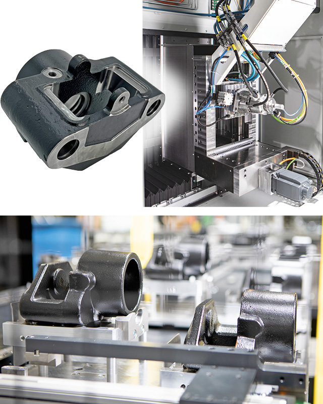
Powerful chip removal via robust tool drives

Cycle time: one component in 240 seconds
The cast blank of the brake caliper is machined on the front and rear side via the opposing horizontal work spindles.
The machine is loaded via a feeding belt which is designed as an accumulating belt. The housing blanks do not lie directly on the belt. In order to feed them into the machine in a defined position, two blanks are inserted into each pallet; the two blanks to be machined have a slight difference in height within the pallet. This double occupancy of the pallet shortens the accumulation belt and still offers a machine self-sufficiency of a good 2 hours.
The loading gantry with pneumatic gripper picks up the cast blank from the pallet and places it directly into the special chuck.
Centring pins on the chuck ensure the correct positioning of the brake caliper housing. In addition, the jaw stroke of the chuck is controlled by the clamping travel monitor mounted on the spindle.
This type of transfer enables error-free contact and centring within the chuck, ensuring that the blank is machined to OP10 in accordance with the defined reference surfaces and holes.
The balanced chuck, in combination with the spindle speed of 1600 min-1, leads to an excellent machining result.
A special feature of the machine concept described here are the Y-axes of the main spindle units. These axes enable the tool block to be very compact on both the OP10 and the OP20, as the tools are arranged one above the other.
This also has the advantage that the travel distances from tool to tool are minimal.
The process-integrated measuring probe is used to measure quality-relevant parameters (length, diameter) of OP10. These data are used for tool correction; they also serve to ensure the process quality for further processing of the component on OP20.
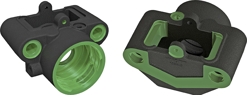
green = processed areas
Highlights
Complete machining of the cast housing in two set-ups on one machine bed
Direct workpiece transfer from main spindle OP10 to OP20
5 driven tools in OP10
Clamping path monitoring in OP10
15 driven tools in OP20
Air system control in OP20
Work spindles with X,Y,Z and C axis
Travel/cycle time optimised tool arrangement in X and Y direction
Driven tools with HK-CON motor spindles for highest cutting performance, vibration reduction and internal tool cooling
Optimised, strong guides in X- and Z-axis with robust bearing package for maximum machining forces
Cycle time 240 seconds
Two-lane unloading conveyor
Loading: unmachined parts directed via pallet dust conveyor and 2-axis loading gantry, 30 workpieces
Measuring probe in the work area for quality assurance of the inner radius, coupled with tool correction and measurement of the fit for OP20
Direct workpiece transfer from spindle to spindle
OP10
13 tools, 5 of which are driven, machine the brake caliper in OP10 from the cylinder side. In this set-up, with the brake cylinder centric to the work spindle, the internal turning steels, boring bars and back boring bars create the contour of the brake cylinder inner surface. Cylinder surfaces with different diameters, annular grooves and flat surfaces are produced. In contrast, the driven face milling cutters, step drills, reamers and deburring cutters machine the off-centre flat surfaces, bores and fits for the two slide pins.
The fit of the brake cylinder inner wall produced on OP10 is used as the clamping surface in OP20.
After completion of the machining process in OP10, the housing is transferred directly from the main spindle OP10 to the main spindle OP20, which is equipped with a clamping arbor including air system control.
The motor spindle of OP20 is equipped with an additional spindle brake to stabilise the C axis. It is used to absorb the high torques during machining.
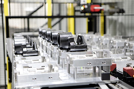
30 parts self-sufficiency – infeed conveyor as pallet dust conveyor
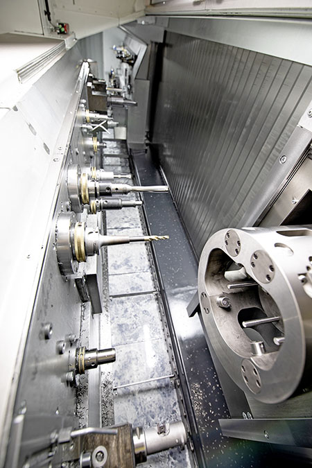
5 driven tools in OP10

Special chuck OP10
OP20
The rear machining of the brake calliper is carried out using 15 driven tools. The end mills, ball mills, disc mills, drills, taps and deburring tools are used to produce the assembly stop and the brake pad sliding surfaces, the retaining bracket lock as well as the venting and hydraulic connection.
In order to absorb these large forces that arise during machining, the guides of the X and Z axes are reinforced on both sides. A particularly powerful bearing of the main spindle optimally absorbs the machining forces.
After completion of the machining process, a pneumatic unloading gantry removes the finished housing from the mandrel and places it on a 2-track unloading belt.
The two-track design was chosen due to the restrictive space conditions at the final location.
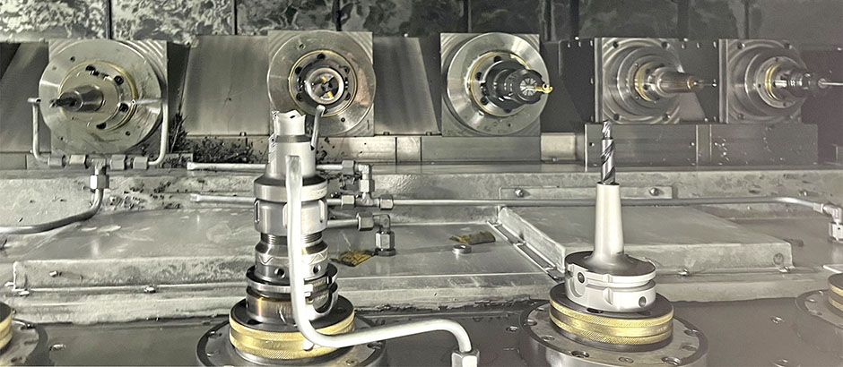
15 driven tools in OP20
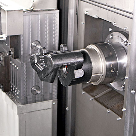
Workpiece on clamping mandrel OP20 for backworking
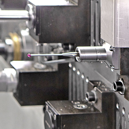
Measuring probes for quality assurance
Technical data / equipment
- 2 work spindles 23 kW, 130 Nm, maximum 7100 min-1
- Travel per work spindle:
- X: 2940 mm
Y: 220 mm
Z: 340 mm - 1 special chuck with stop, 1 clamping mandrel
- 20 stationary, driven tools Tool holders of the driven tool
- 7 HSK-C 40
13 HSK-C 63 - Power data of the driven tools:
14,6 kW / 35 Nm
8,9 kW / 16 Nm - 8 fixed tools, Capto C5
- Sinumerik 840 D SL
- Central lubrication
- Cooling lubricant system with compact belt filter and immersion cooler
- Chip conveyor
- Exhaust air unit
- Hydraulic system
- Dust conveyor with pallets
- Unloading conveyor
Options
- Visualisation Tool management
- User interface
- Tool breakage monitoring
Machine dimensions
- Dimensions of the main machine (L/W/H): 7084 mm / 3480 mm / 2870 mm
- Machine dimensions incl. peripherals (L/W/H): 10960 mm / 6740 mm / 3740 mm
