Stator ring jacket machining plant
Cycle time 86 seconds
- Machining of inner, outer and end shields on one machine bed
- 3 motor spindles
- Direct transfer from spindle to spindle
- Simultaneous machining of 3 components in 3 operations
- Outer diameter < 300 mm, length < 300 mm
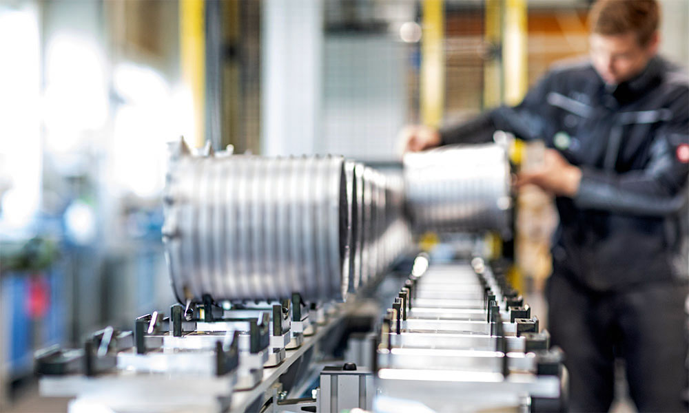
Maximum process reliability, clearly structured tools and chip removal, intuitive parameterisation of the individual machining steps with the shortest cycle time on one machine bed.
Processing machine, loading and unloading conveyor, gantry loader, robot handling, quality assurance, automation sequence, clamping devices, tools and technology – all from a single source and optimised by HK-CON.
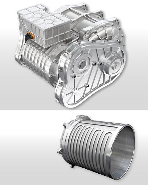
More info on workpieces
Complete machining
26 operations in three set-ups
The flatbed design of the machine bed features a welded frame construction, which serves to uphold the machining assemblies and counteract the forces produced during operation. Incorporating ribbing into the bed ensures sufficient rigidity, thereby facilitating smooth and low-vibration machining processes.
Along the length of the bed, in three sections, the X-axis guides are mounted with the Z-axis guides arranged orthogonally on them. This arrangement leads to the 3 cross slides that support and position the 3 horizontal work spindles. The linear axes are equipped with absolute length measuring systems – glass scales. The alternating arrangement of the X-axes with overlapping travel paths enable the spindles to transfer components in a secured axial and radial position. The mobile or stationary tools are located opposite the spindles. Depending on the machining task (milling, turning, drilling, reaming), 4 fixed tools are driven by a motor. The clamped workpiece is machined via the spindle axes (X, Z and C) on the positionable or fixed tools.
Shafts arranged centrally between the tool carrier and the X-axes guide the falling chips for discharge from the machining area onto the conveyor belt near the floor. The cooling lubricant is also fed back through these shafts to the coolant system with its belt filter and pumps.
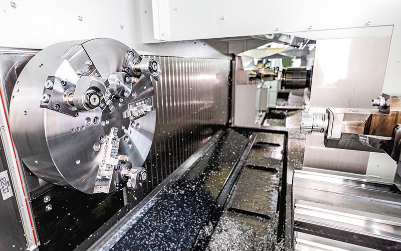
Machining area with mandrel
Highlights
automatic feeding incl. alignment
centric clamping
complete machining in 3 operations
direct transfer from spindle to spindle
100 % measurement incl. downstream automatic tool correction and incl. laser station
simultaneous machining of inner and outer contour
simultaneous machining of 3 components
All-round carefree package: turnkey from a single source
Perfectly coordinated: Loading, processing, cleaning, quality assurance, unloading
The cast blank of the stator ring shell with end shield is efficiently machined to the required accuracies in three operations on one machine bed. Without the end shield, the outside diameter of the shell is 285 mm, the inside diameter 270 mm and the shell length 300 mm.
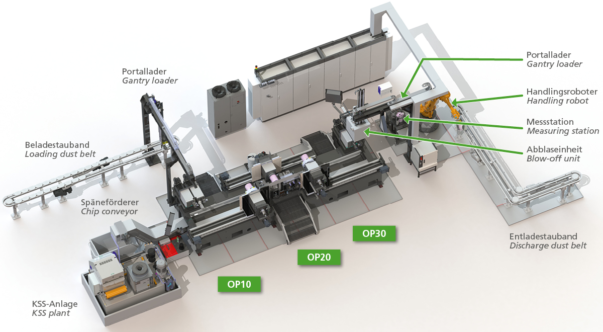
The loading conveyor carries the component over pallets to the transfer position of the gantry loader. The loader picks up the blank, feeds it into the machining area via its travel paths and transfers it precisely to the face chuck of the work spindle of machining position 10.
Operation 10: Roughing of inner and outer shell surface, facing of end faces, machining of bearing hole
Opposite the clamped ring shell are two independent tool carriers that can be moved in the X and Z axes. Tool carrier 1 is equipped with a holder for 2 cutting inserts for external ring machining, while tool carrier 2 has a holder with 4 cutting edges for internal machining and, via a separate holder, the grooving tool for the outer ring groove on the stop side. Due to the travel paths of the work spindle and the tool carriers, roughing of the outer and inner surfaces of the shell is possible at the same time. Further cutting inserts of the inner tool holder perform the facing of the inner side of the end shield and the machining of the central rotor bearing seat. Facing of the shell end face is carried out by means of a cutting insert of the toolholder for external machining. Finishing the ring groove with the grooving plate completes OP10.
The component is then transferred from the face chuck to the mandrel of the motor spindle from machining position 20.
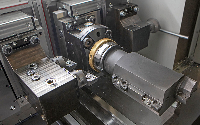
Tools OP10
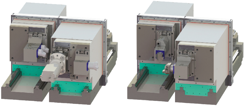
OP10 and OP30 – identical structure, different functions
Operation 20: Machining of outer shell stop with taper centring, main bearing seat, secondary bearing seat and bore
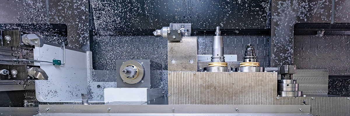
Tools OP20
The 8 tools of OP 20 are fixed in position, 4 of these tools are driven. The cutting inserts of the turning tools rough and finish the outer shell stop and end faces of the end shield. The grooving tool cuts a second annular groove in the shell. The external machining of the rotor bearing seat, the production of a bore and the auxiliary shaft bearing seat as well as that of a reference groove are carried out by 4 driven milling cutters or a reamer. With OP20, the bearing shield of the ring shell is finished.
The clamping mandrel transfers the component to the face chuck of OP 30.
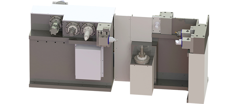
OP20: Multifunctionality, compact design
Operation 30: Finishing the outer and inner surfaces of the shell and the bearing seat
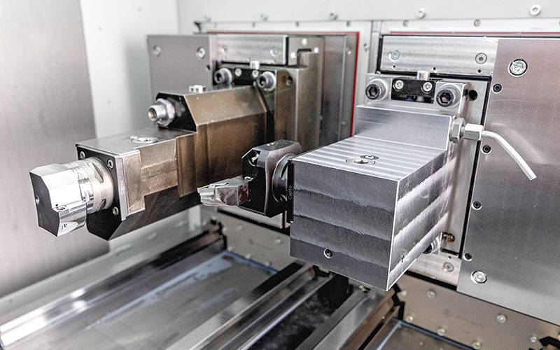
Tools OP30
The tool structure of OP 30 with its two tool carriers that can be moved in the X and Z axes corresponds to that of OP10. Each tool carrier is equipped with a cutting insert via a holder. These take over the simultaneous finishing of the inner and outer surfaces and subsequently the finishing of the bearing seat and the end faces. The machining of the component is finished with the finishing.
Intelligent detailed solutions
Face chuck (HK-CON in-house development) and clamping arbor
Hydraulic clamping chuck with stop, centring and air system control.

HK-CON Face chuck
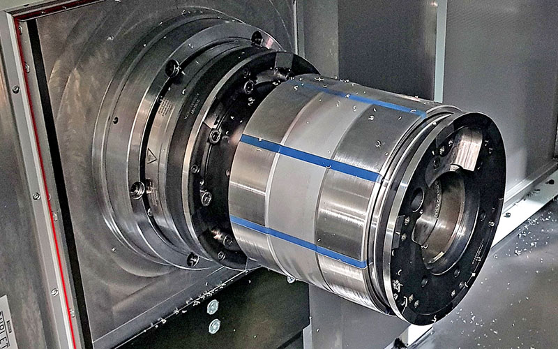
Clamping mandrel with stop and air system control
Gantry loader for placement and removal
The second gantry loader picks up the component in OP30 and transports it via the blow-off unit to the intermediate station of the test and final loading area. Two NC axes in conjunction with a pneumatic gripper perform the assigned functions for each gantry.
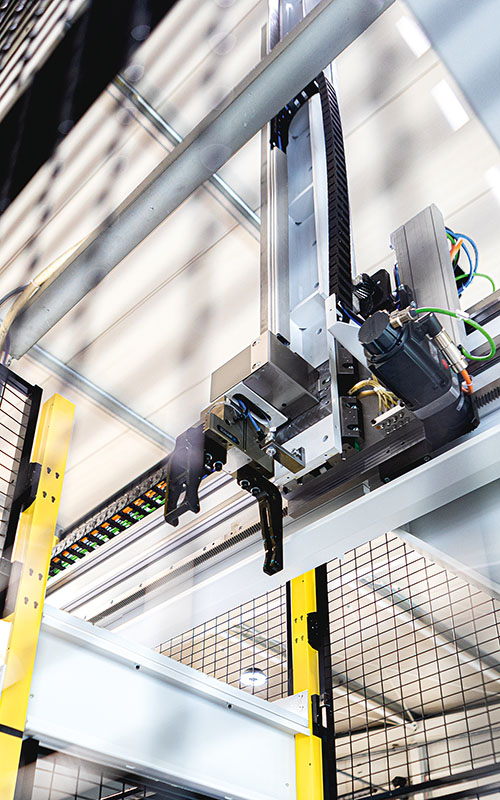
Gantry loader placement
Blow-off unit
The blow-off unit is placed on top of the working area of OP30 and separated from the machine room and the environment by two bulkheads. The outer surfaces are cleaned of cooling lubricant by means of fixed nozzles and the inner surfaces by means of the guided nozzle lance with compressed air.
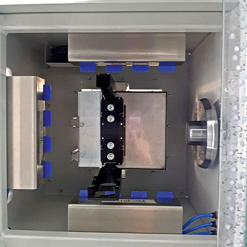
Abblaseinheit, rechts fahrbare Düsenlanze
Handling robot and measuring station
From the intermediate station, the industrial robot guides the stator ring shell via the measuring station to the pallet of the unloading conveyor, which feeds the component out of the safety area for laser marking. The results of the measurement are used for tool correction in the CNC. The pallets of the unloading conveyor are equipped with RFID transponders for clear identification. When the component is placed on the pallet, the transponder is written with the production data. The laser marking station reads out and resets the transponder.
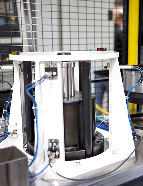
Measuring station
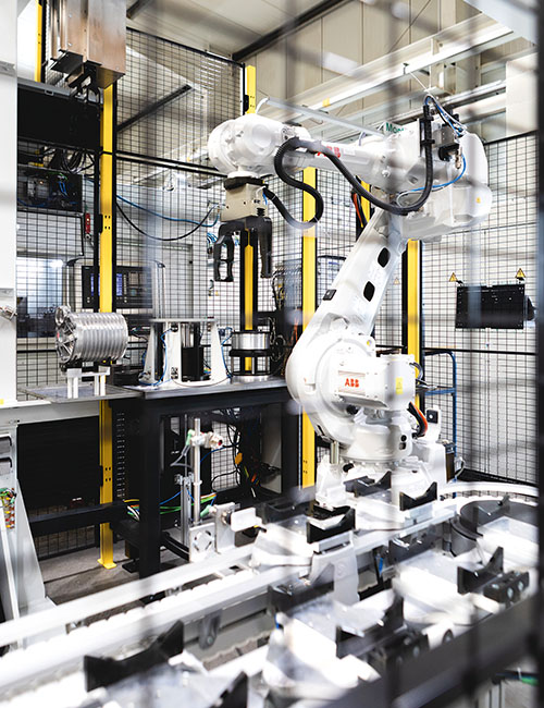
Measuring station with handling robot
Loading, unloading dust belt
… with 30 pallets each
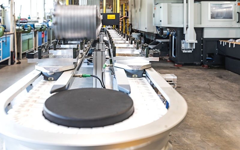
Loading conveyor, loading by hand
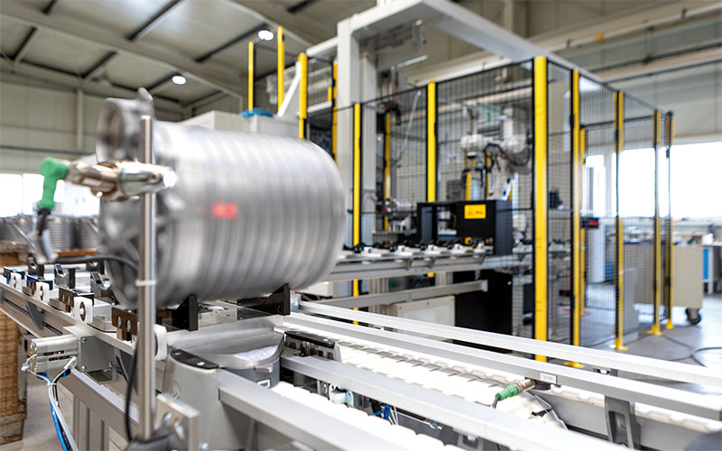
Unloading dust belt
Technical data | Equipment
- 3 work spindles with 104 kW each, 585 Nm 1700 min-1
- Travel per work spindle
X1/X3: 2010 mm
X2: 2260 mm
Z: 340 mm - 2 hydraulic chucks with stop, centring, air system control
- 1 clamping mandrel with stop and air system control
- 4 fixed driven tools HSK 63 6000 min-1
2 x 8,9 kW, 16 Nm
2 x 20.3 kW, 50 Nm - 4 fixed tools Capto C5
- 5 movable tools for parallel external and internal machining
1 x tool Capto C5 movable in Z-direction (410 mm)
3 x tool Capto C5 movable in Z-direction (410 mm) and X-direction (50 mm)
1 x tool movable in Z-direction (410 mm) and X-direction (50 mm) HSK 100 - 1 loading gantry (travel in Z direction: 3550 mm, Y direction: 1615 mm)
- 1 unloading portal (travel X-direction: 2500 mm, Y-direction: 1615 mm)
- 1 blow-off unit integrated in cladding (approached by unloading gantry)
- 1 intermediate deposit
- 1 measuring station
- 1 loading dust conveyor with 30 pallets, conveyor loaded manually, removed from gantry
- 1 unloading dust conveyor with 30 pallets with RFID memory for data transfer to tracked laser labelling
