4-spindle turning centre for toothed, bevel, chain and shift gears
Fully automated production cell
- Simultaneous use of 4 main spindles
- Front and rear machining
- 4 driven tools for drilling, milling
- Cycle time: 2 components in 60 seconds

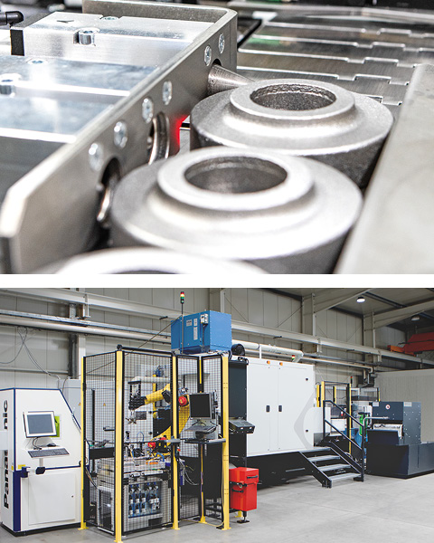
Precision with high output and user-friendly operation

4 Spindle turning centre for front and rear machining of toothed, bevel, chain and shift gears
The flatbed design of the machine features a welded frame construction for supporting the machining assemblies and dampening the process forces. Ribbing incorporated into the bed ensures the requisite rigidity for smooth, low-vibration machining operations.
Along the length of the bed, in two sections, the X-axis guides are mounted with the Z-axis guides arranged orthogonally on them. This arrangement leads to the 2 cross slides that support and position the horizontal double spindles (synchronous spindles). Glass scales are used as an absolute length measuring system for the linear axes. The alternating arrangement of the X-axes with overlapping travel paths enable the double spindles to transfer the workpiece in a secured axial and radial position, thus enabling front and rear machining of the workpiece. On 2 levels, opposite the double spindles, the fixed tools are located on solid supports. The eccentric holes of the workpieces are produced by the 4 fixed, driven drills. Each spindle is assigned a driven tool. The clamped workpiece is machined completely on the fixed tools via the spindle axes (X, Z and C).
Sliding guides with roller drive between the tool levels in the X-axis and sliding guides between the synchronous spindles/double spindles in the Z-axis enable tool compensation combined with accuracies of 0.005 mm.
Shafts arranged centrally between the tool carriers and the X-axes of the double spindles guide the falling chips to the conveyor belt near the floor for discharge from the machining area. The cooling lubricant is also fed back through these shafts to the coolant system with its belt filter and pumps.

Four workpiece programmes
- Ø 97 mm x 29 mm
- Ø 88 mm x 36 mm
- Ø 136 mm x 41 mm
- Ø 145 mm x 40 mm
Highlights
Simultaneous machining of 4 workpieces
4 simultaneously operating main spindles
Front and back machining
High cutting forces
Fixed tools for low-vibration machining – long tool life
Short chip to chip time
Loading
The industrial robot installed in the loading area first separates the workpieces from the bulk material using the bin-picking method (reaching into the box). Subsequently, the indexing/resting wheels on the loading conveyor are fed to the orientation unit for rotary layer alignment via stopper and pneumatic driver.
The swivel gripper picks up the aligned part and feeds it one after the other to the two superimposed grippers of the loading gantry. Loading ends when the grippers move to the transfer position opposite the double spindles of OP10.
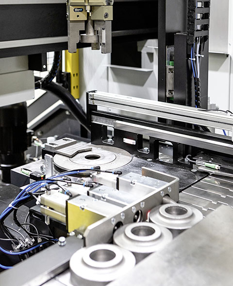
Loading conveyor, stopper and pneumatic carrier (top), robust loading
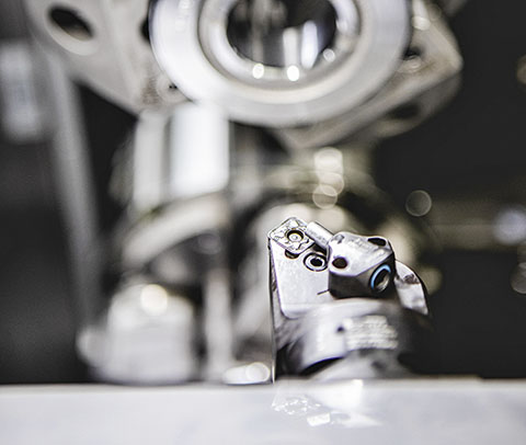
Fixed tools for high cutting forces
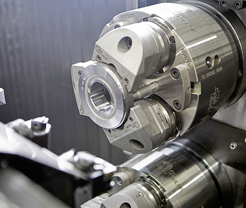
The workpiece firmly in hand, the collet chuck
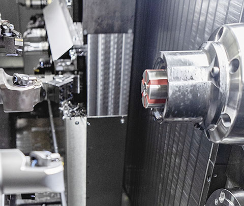
Clamping mandrel with powerful main spindle
Operation 10: Centre hole making, roughing, finishing of plane, inner and outer surfaces
Fixed to the outer surface of the shell by the three-jaw pull-down chucks of the double spindles, the two forging blanks are machined at the front in OP 10:
- Drilling of the shaft hub and production of the internal fit
- Roughing and finishing of 2 radial flat surfaces with contour
- Chamfering of the shaft fit on the rear side
- Countersinking of 7 eccentric holes between the webs
- Rolling in of marking
- Turning of the available outer shell part surface
After machining, the spindles of OP10 transfer the blanks in the cutting area of both X-axes to the segment mandrels of the double spindles of OP20. The transfer takes place in a defined axial and radial position.
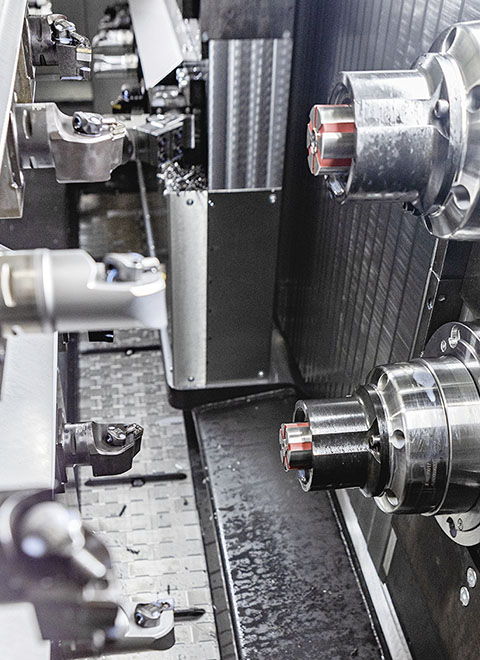
Machining space, clear tool structure
Operation 20: Roughing and finishing of face and shell outer surface, setting of eccentric holes
The segment mandrels with stop – all clamping devices are equipped with air system control – hold the workpieces on the manufactured shaft hub and enable the following backworking:
- Roughing and finishing of the outer shell
- Roughing and finishing of 2 radial flat surfaces with contour
- Drilling of 7 eccentric holes between the lands
Die zerspanende Bearbeitung der Teile ist beendet und die Segmentspanndorne übergeben an das Entladeportal.
Unloading: parts removal, cleaning, quality assurance, labelling
The unloading gantry removes the parts from the machining work area and makes them available to the industrial robot of the control area for the downstream activities. To optimise the travel paths in conjunction with short transport times, this is equipped with a double gripper.
The parts pass through the stations via the robot’s handling functions:
- Blow-off and cleaning unit
- Measuring and quality assurance station
- Measuring part ejection for SPC parts, separate for each spindle level
- Laser marking
- Unloading conveyor or washing machine
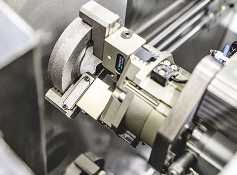
Gripper of the loading, unloading portal
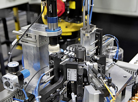
Quality inspection – placement and removal by robot
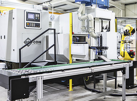
Unloading belt
Standard equipment
- 4 work spindles, 23.1 kW, 130 Nm, 7000 rpm, water-cooled
- Travels of the synchronous spindles: X: 1500 mm, Z: 240 mm
- 2 U-axes for correction between upper and lower tools
- 2 W-axes for correction between the synchronous spindles
- 2 collets, 2 mandrels
- 18 fixed tool holders Capto C4
- Embossing tool OP10
- 2 driven tool spindles HSK-C 63 with 14,6 KW, 35 Nm, 4500 rpm OP10
- 2 driven tool spindles HSK-C 63, 20.3 KW, 50 Nm, 4500 rpm OP20
- Machine control Sinumerik 840 D SL
- Central lubrication
- KSS with compact belt filter and immersion cooler
- Chip conveyor
- Fog extraction system
- Hydraulic system
- Industrial robot
Options
- Visualisation Tool management
- User interfaces
- Tool breakage monitoring
- Motor spindles with rotary feed-through for tools with internal cooling lubricant supply
Machine dimensions
- Machine tool incl. periphery: 15000 mm x 5000 mm
