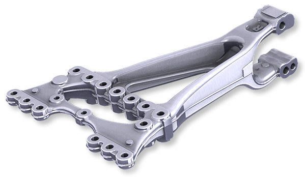
Four-axis horizontal transfer production line Axle bearing block
Highly productive production of truck axle bearing pedestals or trailing arm pedestals using three machining stations – with simultaneous machining of the workpiece on both sides
… without loop lashing
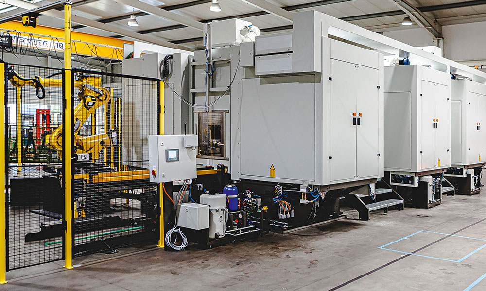
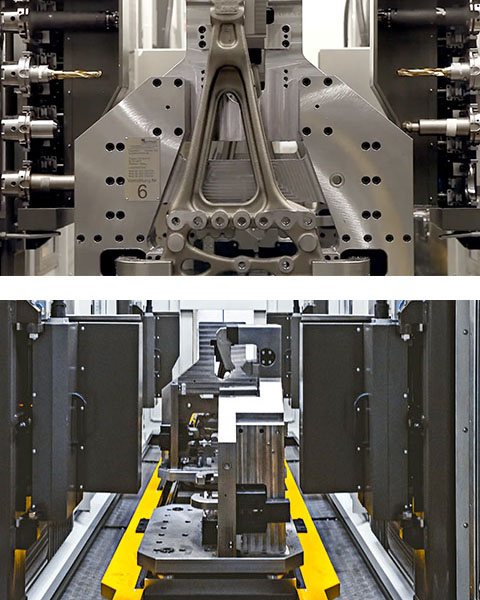
Automated four-sided machining of the trailing arm support of truck wheel suspension
The heart of the four-axis horizontal transfer production system is the simultaneous machining of 3 workpieces in 3 machining stations – each with changing tools on both sides.
All sides of the workpiece are machined in one system to save time.
Further information on workpieces
Suitable for
- Axle bearing blocks, trailing arm blocks
- Trailing arms, wishbones and four-point links, stabilizers
- Large-volume cast, forged and welded parts of the wheel suspension and frame construction
- Battery bases, lids, trays and housing parts for electrical controls and converters
- Gearbox, valve and electric motor housings
Terms of reference
- Face milling of surfaces on the front and back
- Production of through holes
- Thread cutting
- Deburring and countersinking of holes
- Editing contours
Special feature
- The complete machining process takes place in one machine
- Very short transport distances of the workpiece
- The workpiece is machined in only one clamping
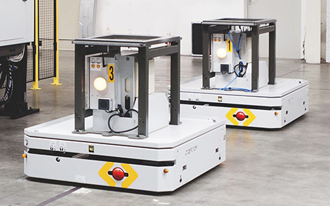
Driverless transport trolleys on induction loops
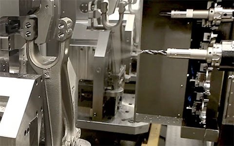
Cleaning before tool change
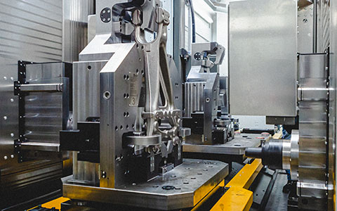
Processing on both sides – simultaneously at three processing stations
Equipment
- 3 machining stations with 2 milling spindles each (= 6 milling spindles)
- 3 tool axes + B axis, optional A axis
Tool spindle
- Tool holder: HSK 100
- Internal coolant supply up to 120 bar possible
- Tool magazine: 4 tools per spindle, expandable
- Torque: 250 Nm / 3000 min-1
- Output: 34,2 kW
Periphery equipment
- Loading and unloading with robot
- Driverless transport system
- Integration of customer supplies (e.g. measuring station, deburring station, …)
Machine dimensions
- Transfer production line: 1400 mm x 6500 mm
- With driverless transport system, loading and unloading: 22000 mm x 14100 mm
Machining area
- Tool path:
- X: 707 mm
- Y: 700 mm
- Z: 490 mm
Highlights
Operation of the entire transfer production line by only one operator.
Six machining operations with one control.
Radio pressure monitoring of the clamping pressure with display output.
RFID chips: unique identification of all nine pallets in use. This enables the control system to automatically compensate for the zero offset of each individual pallet.
All tools are equipped with tool breakage monitoring. Effective tool breakage monitoring also includes the automatic retraction program after a tool breakage. This also applies to the taps.
Reading of the tool data via RFO.
Light curtain with “cut-out”: The carriages of the driverless transport system pass through a light curtain when leaving and when entering the transfer production line. The contours of the trolley are digitally stored. This ensures that no human passenger can enter the loading and unloading area of the machine through the light curtain.
An impressive development of HK-CON is the lifting transport unit. The cylinder used to lift the seven pallets being processed can lift 19 500 kg – including clamping devices and workpiece. The mechanics behind it are solidly constructed. The transfer production machine therefore has a real “powerhouse under the cladding” as a transfer system.
Lead frames (of a MAN tractor unit)
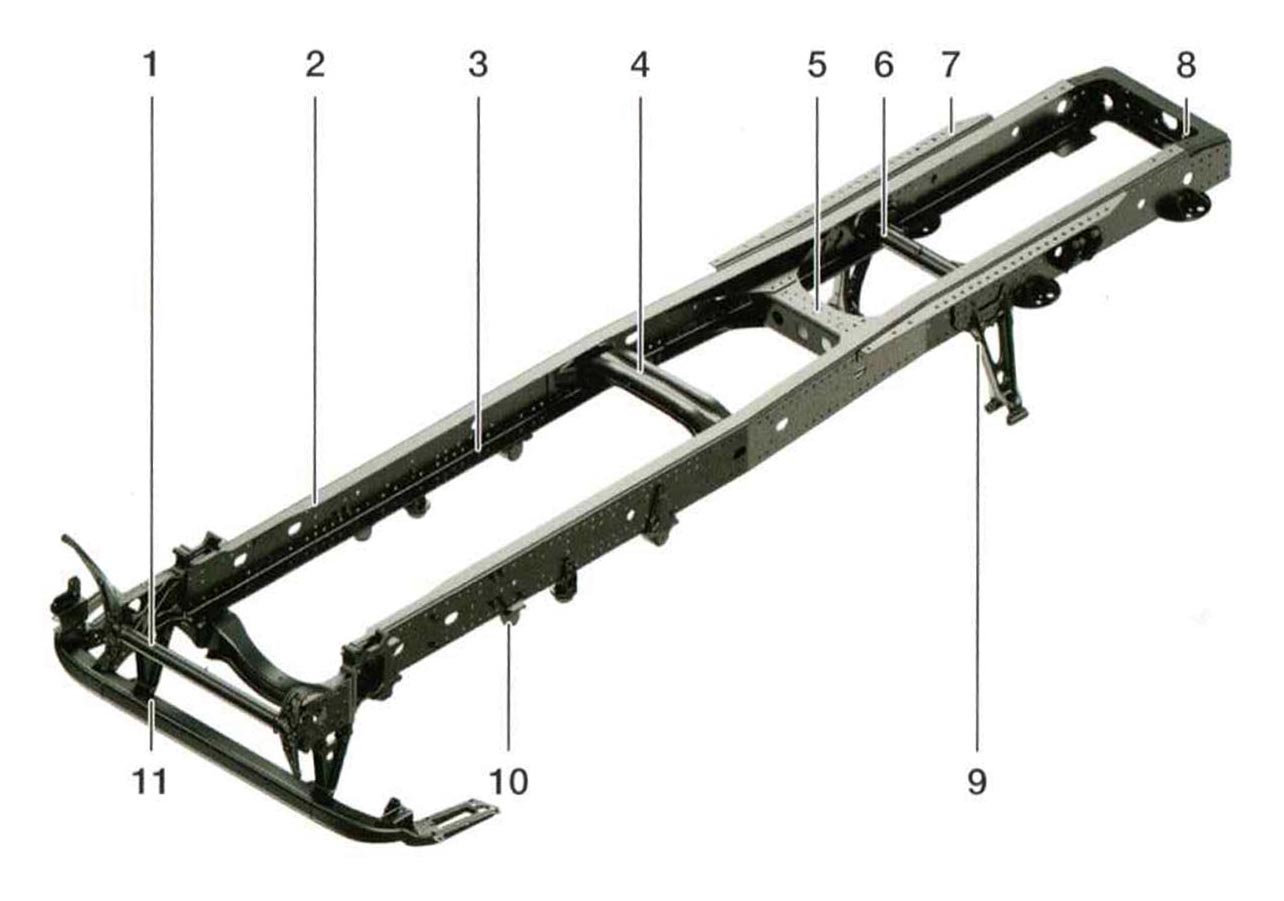
Legend
- Frontend
- Side member (U-profile) with hole grid
- Side member insert (L-section)
- Cross member (top hat profile)
- Main cross member
- Cross member (tubular profile)
- Subframe for fifth wheel coupling plate
- End cross member (for SZM)
- Trailing arm bracket (with air suspension)
- Shock absorber console
- Front underrun protection
Source:
Grundlagen der Nutzfahrzeugtechnik
LKW und Bus – Lehrbuch der MAN Academy
4th edition 2016
ISBN 978-3-7812-1994-6
With kind permission of
© MAN Truck & Bus
Dachauer Straße 667, 80995 München
www.man.eu
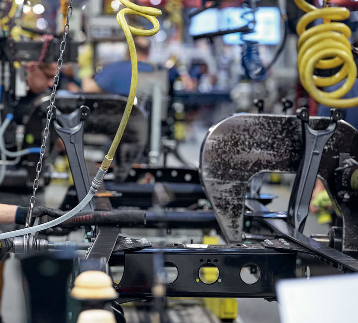
Assembly of axle bearing blocks in the MAN truck plant in Krakow
With friendly permission of
© MAN Truck & Bus – www.mantruckandbus.com
Experience the transfer production line TFA-3-2 in action
The machine concept: quality, quantity, reliability
Loading and Unloading
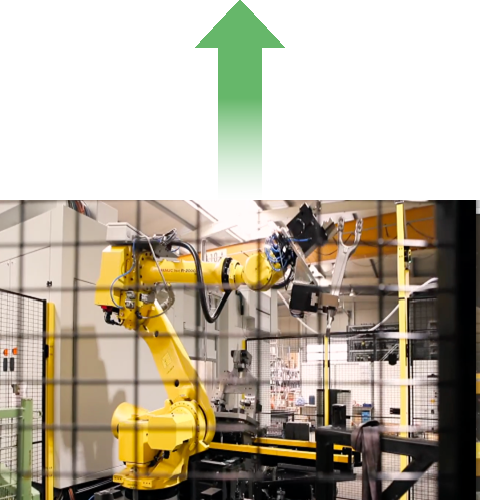
A Fanuc robot programmed by HK-CON is used for loading and unloading. A comparable robot of the manufacturers Yaskawa, Stäubli, KUKA and ABB can also be used.
There are no limits to customer requirements.
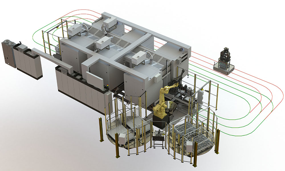
The machine is loaded and the finished workpiece is unloaded with the aid of only one robot – in combination with the integration of a driverless transport system: this returns the machined bearing block to the loading periphery fully automatically.
Thus, the loading and unloading area coincide. A 6-axis robot from Fanuc with a reach of 2655 mm and a load capacity of 165 kg is used for loading the clamping device and for unloading the trolleys of the driverless transport system, which was also integrated into the process by HK-CON.
The Fanuc robot R-2000iC/165F is constructively integrated into the overall concept of the transfer production system. The programming of the motion sequences during loading and unloading, including feeding into separate deburring and measuring units, is also part of HK-CON’s know-how!
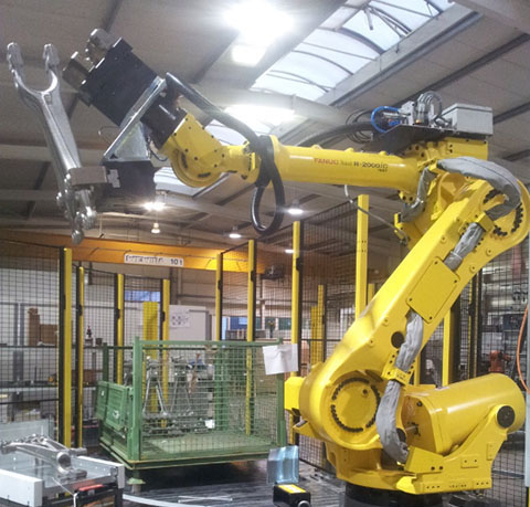
Fanuc robots for loading and unloading
Rotary tables – for effective loading
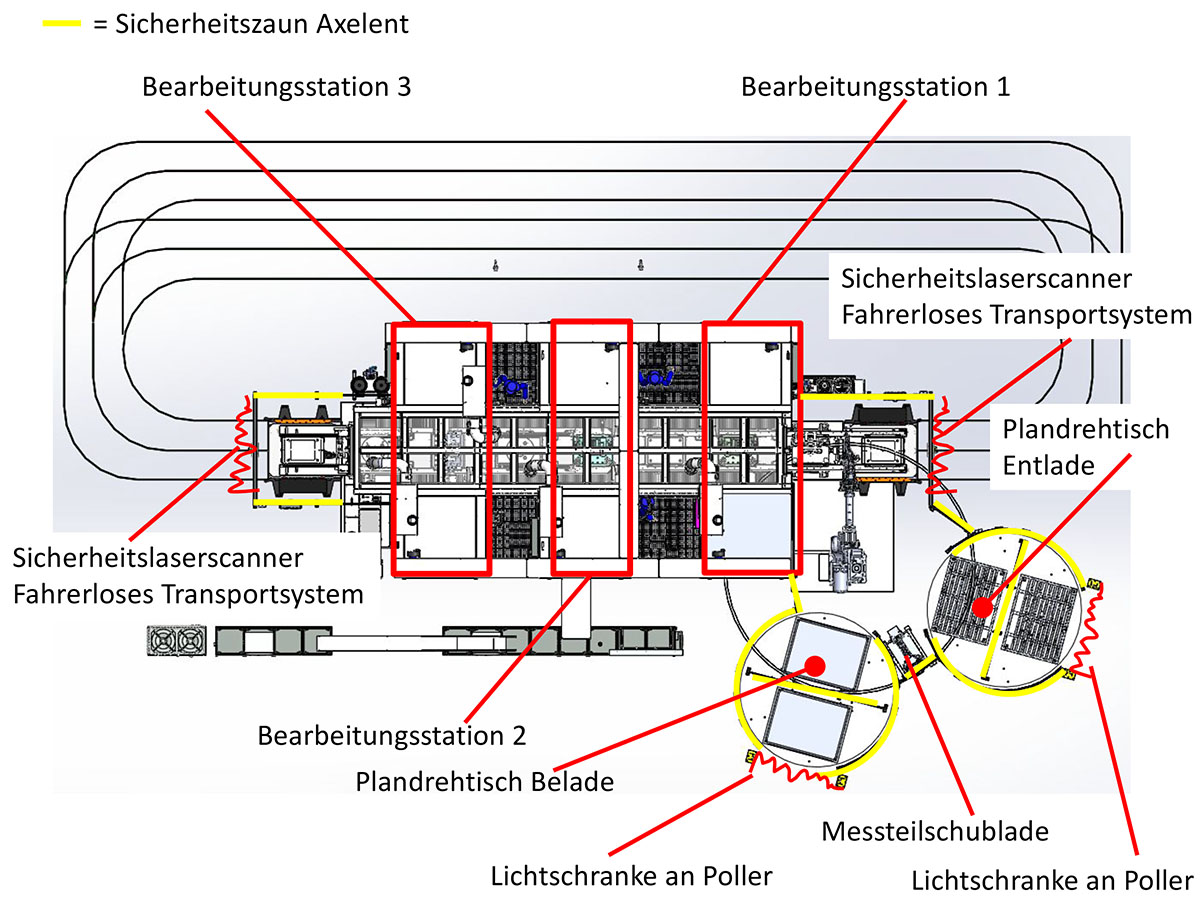
The raw parts sorted into charging pallets are transported into the robot room via a turntable.
This has two functions
- The robot loads the system from a pallet
A second pallet serves as parts storage for stocking
The pallets are lifted onto the turntable by means of a forklift truck.
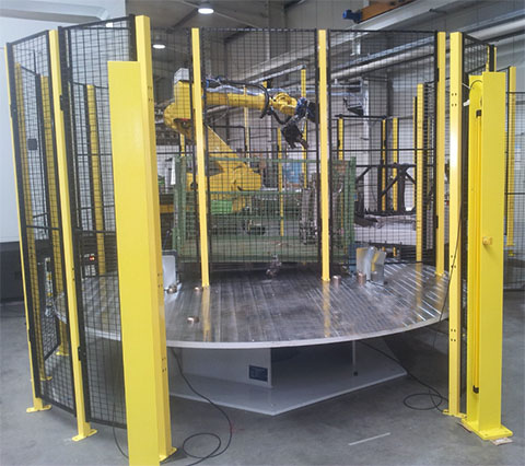
The turntables enable effective working
Safety devices
On the one hand, the turntable creates a secure boundary between the robot room and the environment. The fence elements provide protection against unintentional entry into the robot room.
Furthermore, the system has a system-specific safety concept which has been checked by an independent company and confirmed by a risk assessment or the declaration of conformity.
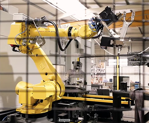
Protected behind bars
Clamping device and lifting transport unit
The robot removes the workpiece in its working area and places it in the machine’s clamping device. The clamping device is slightly tilted backwards in this 0th station to ensure safe insertion and positioning of the workpiece.
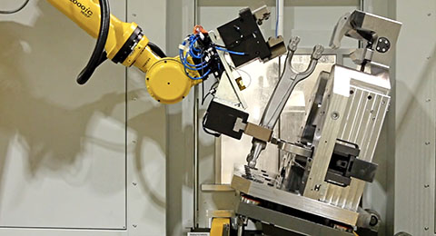
Slight inclination for safe insertion and positioning of the workpiece
Three processing units
In total, the horizontal transfer production line has three machining stations in which the workpiece is simultaneously machined on both sides. The workpiece is transported between the machining stations by the lifting transport unit. This unit connects the three machining stations with each other, whereby the entire assembly “clamping device + semi-finished product” is lifted, moved and lowered on the next station. The special feature here is that the workpieces remain permanently clamped during the entire machining process.
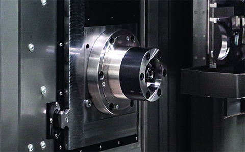
The machine has six turning spindles
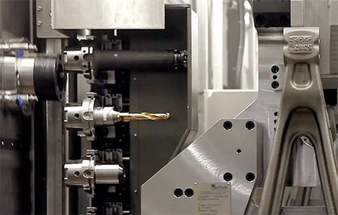
Tool change, 4 times per spindle
Zero-Point Alignment
A zero-point alignment is carried out at each station using the zero-point clamping system. This ensures that the position of the workpiece does not shift during the machining process.
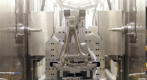
A zero-point alignment is performed at all three machining stations
Lifting transport unit
The lifting transport unit consists, in simplified terms, of two parallel bars which the processing machine passes through along the longitudinal axis of the machine from station 0 (loading station) to station 6 (turning back and cleaning). The lifting transport unit also functions as an unloading device by lifting the assembly “clamping device + finished workpiece” out of the machine onto the carriage of the driverless transport system.
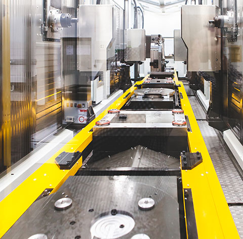
Central lifting transport unit
Eight stations: Fully automated machining of the workpieces
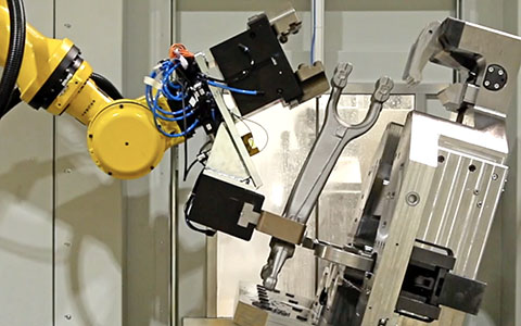
oth station
The robot places the blank into the clamping device.
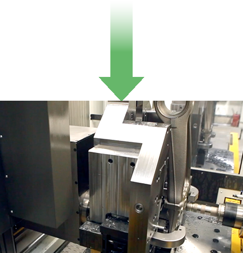
1st station
Processing station 1: The workpiece is processed from both sides: The flat surfaces are first roughened and then finished.
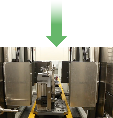
2nd station
This station is an intermediate station during transport – no processing.
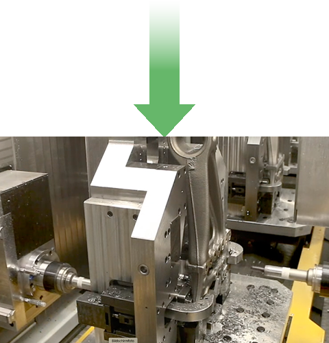
3rd station
Processing station 2: Simultaneous processing on both sides.
- Insertion of the through-holes
- After tool change, cutting the required threads
- At the same time, the holes are deburred on the opposite side
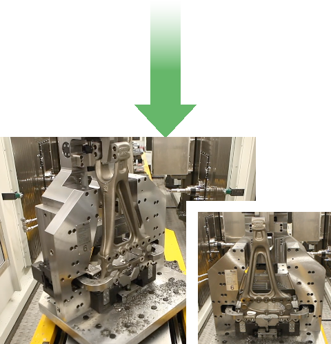
4th station
Intermediate station equipped with a B axis. Here the workpiece is rotated by 90°. This allows the machining of the narrow sides in the following station.
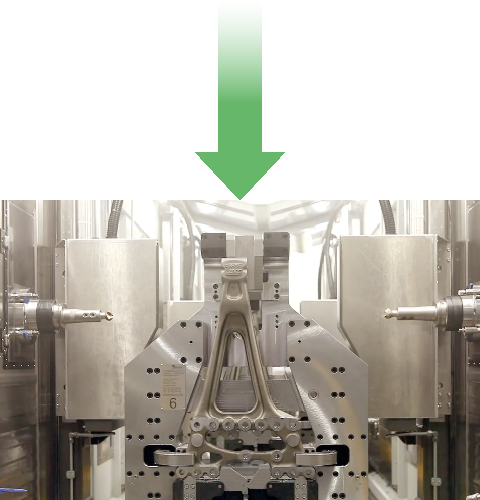
5th station
Machining station 3: The through holes of the narrow sides are produced from both sides.
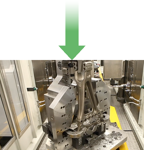
6th station
The workpiece is turned back by 90° using the “station’s own” B-axis.
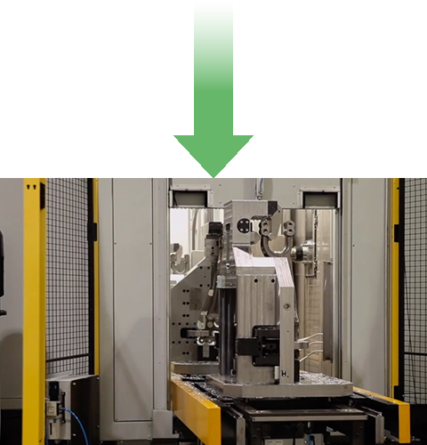
7th station
The lifting transport unit unloads the finished part onto the carriage of the driverless transport system.
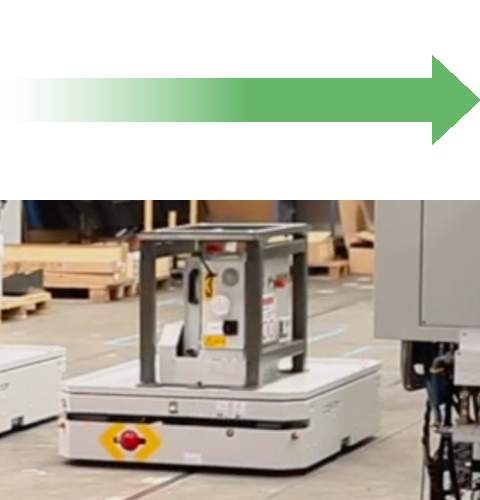
Driverless transport.
oth station
The finished workpiece is removed.
The cycle closes – and begins again …
A carriage of the driverless transport system brings the finished workpiece back to the robot room by means of induction loops on the hall floor.
The robot equipped with a double gripper, which also loaded the system with the blank shortly before, removes the machined workpiece from the clamping device located on the transport carriage and places it in the measuring device. There the workpiece is checked for compliance with all dimensional tolerances. The robot then sorts the finished workpiece into a mesh box for storage of the finished part. This is also located on a turntable, which enables effective and time-saving removal.

