Machining centre for battery frames
Maximum flexibility and productivity
- Short cycle times due to high axis feed speeds
- Powerful motor spindles for powerful chip removal
- Component size 2300 x 1500 x 500 mm
- Tool storage for flexible machining
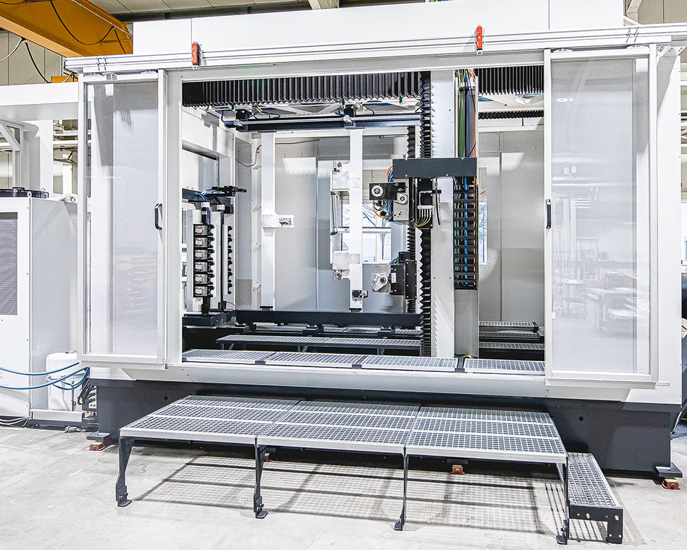
Two-column bed-type milling machine with vertical clamping frame for high throughput
Designed for highest productivity
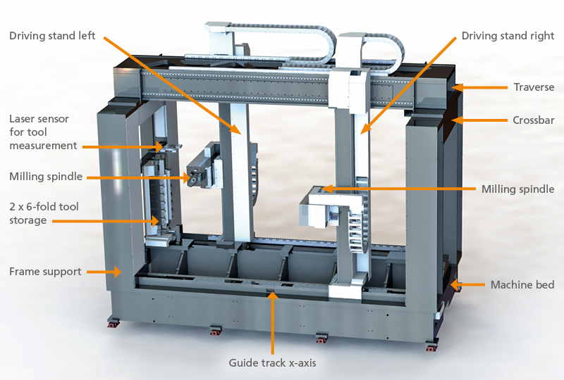
Our double-column bed milling machine with a fixed vertical clamping frame is used for machining battery carriers and frames. This design with the two horizontal main spindles facing each other, suitable choice of tools and clamping devices enables effective machining on the 6 sides. The machine bed is a welded frame construction with high rigidity and high stability.
With the optional NC swivel heads, 5 NC axes are available simultaneously on both the front and rear of the workpiece. Supplemented by tool storage (6,12 or 24) with the changing device, it is a very flexible, precise machining centre for all common manufacturing processes: Milling, drilling, countersinking, thread cutting, reaming, grinding, spindling.
The loading and unloading robot and the workpiece storage units enable this production cell to manufacture parts and assemblies competitively in dry or wet machining.
Further applications
- Large cast housings
- Racks
- welded constructions
- Joined frame and cladding parts
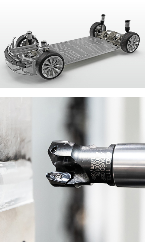
- Battery cases
- Mounting plates
- Aeronautical engineering
- Chassis parts
Highlights
Simultaneous machining through two independent milling spindles<
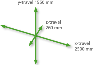
Large workspace 2500 x 1550 x 520 mm
Maximum flexibility through tool storage
Shortest machining times due to high axis feed speeds and powerful milling spindles
Dry, wet machining
Chip-free finished part due to integrated extraction system
Displacement sensor on spindles for optimising component tolerances
High process reliability through laser control of the tools
Automated loading, unloading via robot
See the battery frame machining centre in action

You are currently viewing a placeholder content from YouTube. To access the actual content, click the button below. Please note that doing so will share data with third-party providers.
More InformationYou are currently viewing a placeholder content from YouTube. To access the actual content, click the button below. Please note that doing so will share data with third-party providers.
More Information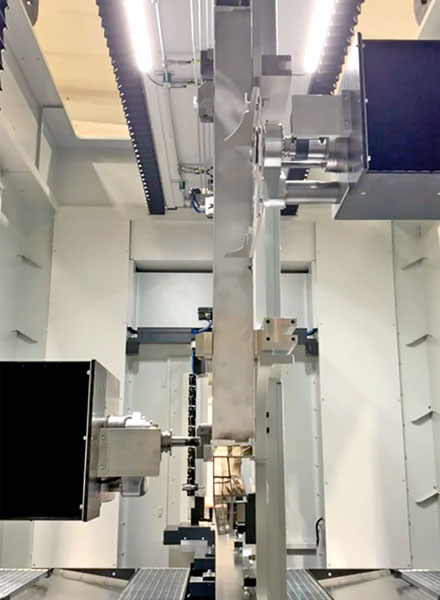
Milling spindle left and milling spindle right (under extraction bell) simultaneously in use on two sides
Loading/unloading
The unmachined truss-shaped battery carrier, consisting of welded aluminium profiles and plates, is inserted and held by the loading/unloading robot in the hydraulic clamping elements of the supporting frame.
Simultaneous editing
The clamping frame functions as a work table and its geometry allows 6-sided machining of the battery frame. The machining task, in this case the milling of the weld seams, is carried out simultaneously by the two opposing motor spindles. Each spindle works autonomously with its own tool memory, a laser-optical path sensor and, for process reliability, a laser system for tool control. This detects tool wear and breakage before and after machining.
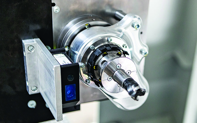
Path sensor and milling spindle with retracted extraction bell
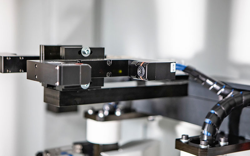
Laser sensor for tool measurement
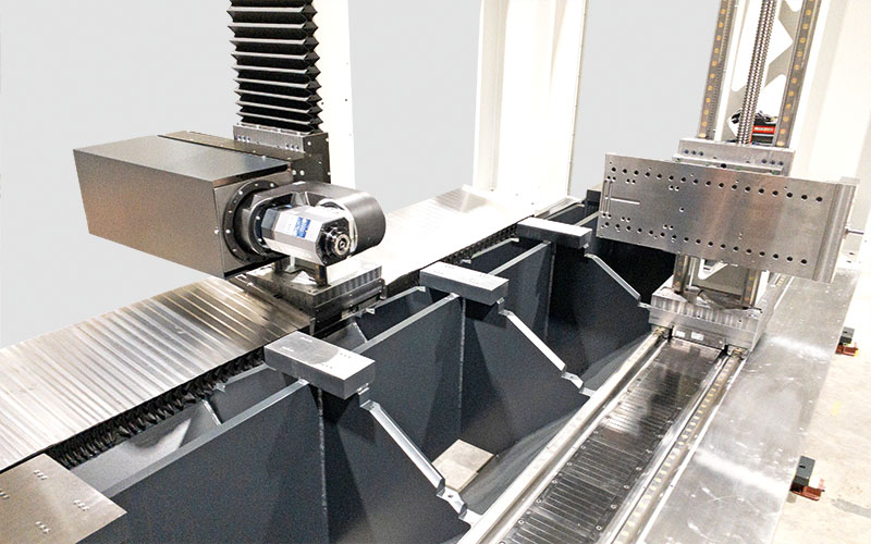
NC swivel head and linear drive x-axis
Permanent extraction of the chips
The switchable extraction bell, which encloses the milling cutter during machining, and further extraction interfaces lead to a chip-free workpiece.
Speed and acceleration
The x-axis is designed with a linear drive.
The spindle units
Milling spindle torque with HSK 50: 20 Nm as standard
Calibration for 100 % precision
The vehicle battery is manufactured in sandwich construction. For the watertight design, the weld seams of the frame girder must be milled down to the level of the profiles. Thus, in a subsequent process, the upper cover and the bulkhead plate can be tightly welded and or glued to the carrier on the later vehicle underside.
To ensure this requirement, the position tolerances of the welding process are compensated with the laser-optical length measurement sensor mounted on the milling spindle. For this purpose, the mean value from 4 measuring points per processing point individually corrects the travel path of the milling spindle.
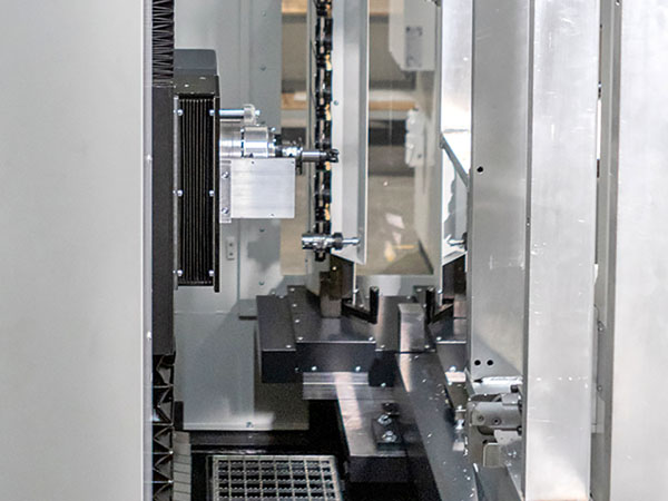
The working area with travelling column (front left), milling head and tool store (rear)
Accessibility
Wide-opening doors and the large workspace offer ideal freedom of movement for robots and operators.
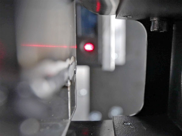
Measurement by laser
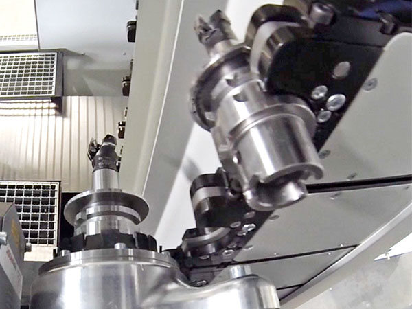
Tool change
Standard equipment
- Travel x/y/z: 2500 x 1550 x 260 mm
- motor spindle power: 9,2 kW
- spindle speed: 8000 rpm
- Torque (max.): 20 Nm
- rapid traverse (x/y/z): 100/30/30m/min
- spindle cone: HSK 50
- Tool storage: 2 x 6 pcs.
- Machine weight: 25,000 kg
- Control: Siemens solution line 840dsl
- Chip conveyor/suction
Special equipment
- NC swivel head
- RFID tool identification
- Second milling stand left/right
- Second clamping frame to reduce cycle time, loading/unloading with simultaneous machining
- Rotary table
- Tool holder HSK-63, HSK-80; HSK-100
- Tool storage 12 pcs. or 24 pcs.
Machine dimensions
- Machine tool incl. periphery: 7500 mm x 3100 m

